
Intro
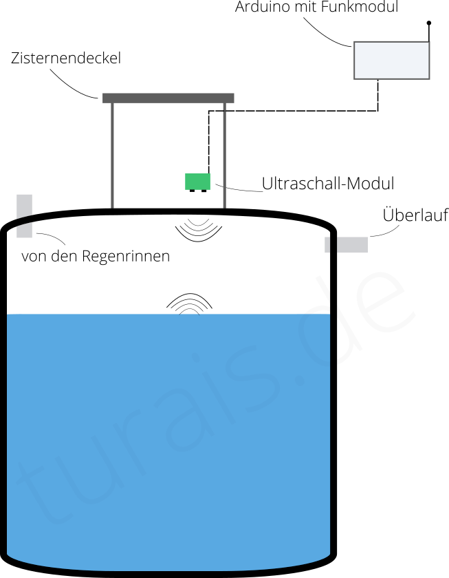
Some years ago I installed a water level sensor, based on an ultrasound sensor. The principal were that I installed an ultrasound module at the top of the cistern and measured the distance to the water surface. Based on that distance I calculated the percentage how full or empty my cistern was.
With the old setup I ran into some problems. Sometimes there were cobwebbs and I had to remove the cobwebbs. This was a real issue, since my cistern is not one of those newer models which can shielded from outside influences. I have a cistern made out of concrete with an concrete top and so on. On the side insects can crawl in and so on.
Documentation
I made an little Docu-Page about the TL231 Water Level Sensor. If your're just looking for a usage of this sensor click here:
https://docs.turais.de/docs/sensors/misc/tl231-water-level-sensor/
I have some blog posts about that, but they're only in German:
- Arduino Zisternenpegelstandsmessung Teil 1
- Arduino Zisternenpegelstandsmessung Teil 2
- Arduino Zisternenpegelstandsmessung Teil 3
Problems with my Ultrasound Sensor
I ran into some problems over the years:
- I compensated the ultrasound measurement with temperature. So that in winter when there is about 4°C/40°F the measurement gets adjusted because sound travels differently based on air temperature.
- For the Ultrasound sensor I used an parking sensor from an car, the kind you can find on Aliexpress very cheaply. I found out that for a proper reading you would need an sensor where you create an ultrasound beam, they have an cone at the end to channel the sound a bit more. This would have been a bit better because otherwise the sound will get reflected too much at the entrance of the cistern.
- When the cistern was full everything was fine, and levels from 100% to 80% were really good detecable. But I got some fail readings when the cistern was at levels below 80%. I used an simple moving average to average out some peaks but that was not enough. You need to do some proper intelligent filtering of false measurements.
- My cistern is made out of concrete and underground. The cistern lid closes not 100% and that is why some spiders find it very interesting in there to build there spider webs. No problem for saving some rainwater for watering the garden, but a real problem for my ultrasound sensor. Spierwebs can accumulate some light dirt and then reflect ultrasound and then your reading is trash. The worst thing is you don't have a way to detect a sensor failure without an camera or something.
- You have to check for your sensor and clean it up from time to time. In my opinion this makes this setup with an ultrasound sensor the least favorable way to read some data.
I was looking at some alternatives but over the years a water level sensor based on a pressure sensor were just too expensive for my little hobby project.
Different Sensor to read Water Levels
There are different ways to measure the water level:
Ultrasound based
- Cheap parking sensor - like I used with an Arduino
- Professional sensor which have an proper ultrasound sensor like the Apollo Ultrasonic Level Sensor
Capacitive based
- 2-Wire based - like the Homematic one. It mearuses the capacitance between two wires. If the two wires are in water the capacitance changes according on how much water flows around the 2 wires.
Mechanical
- Swimming probe - basically a little probe with an weight that swims on the surface. Its connected with an little thread to the top. And based how long the thread is extended it shows how much centimers the probe descended.
Mechanical or electric sensors at different heights
The principle is that you attach different sensors at different heights in your cistern or canister. Depending on how many sensors are triggered you know the water level. You can use water level switches you find on Aliexpress or Amazon and build your own with an arduino. To connect the different switches it is practical to use an IO extension board. Those boards are based on an PCF8574.
- To name on commercial one: M167
Water pressure based
- Water pressure probe - like you find on Amazon or Aliexpress these days. You can descend those probes to the bottom of your cistern and they measure the pressure. Pressure in water changes with the depth.
Liquid Level Sensor
The Liquid Level Sensor is often called:
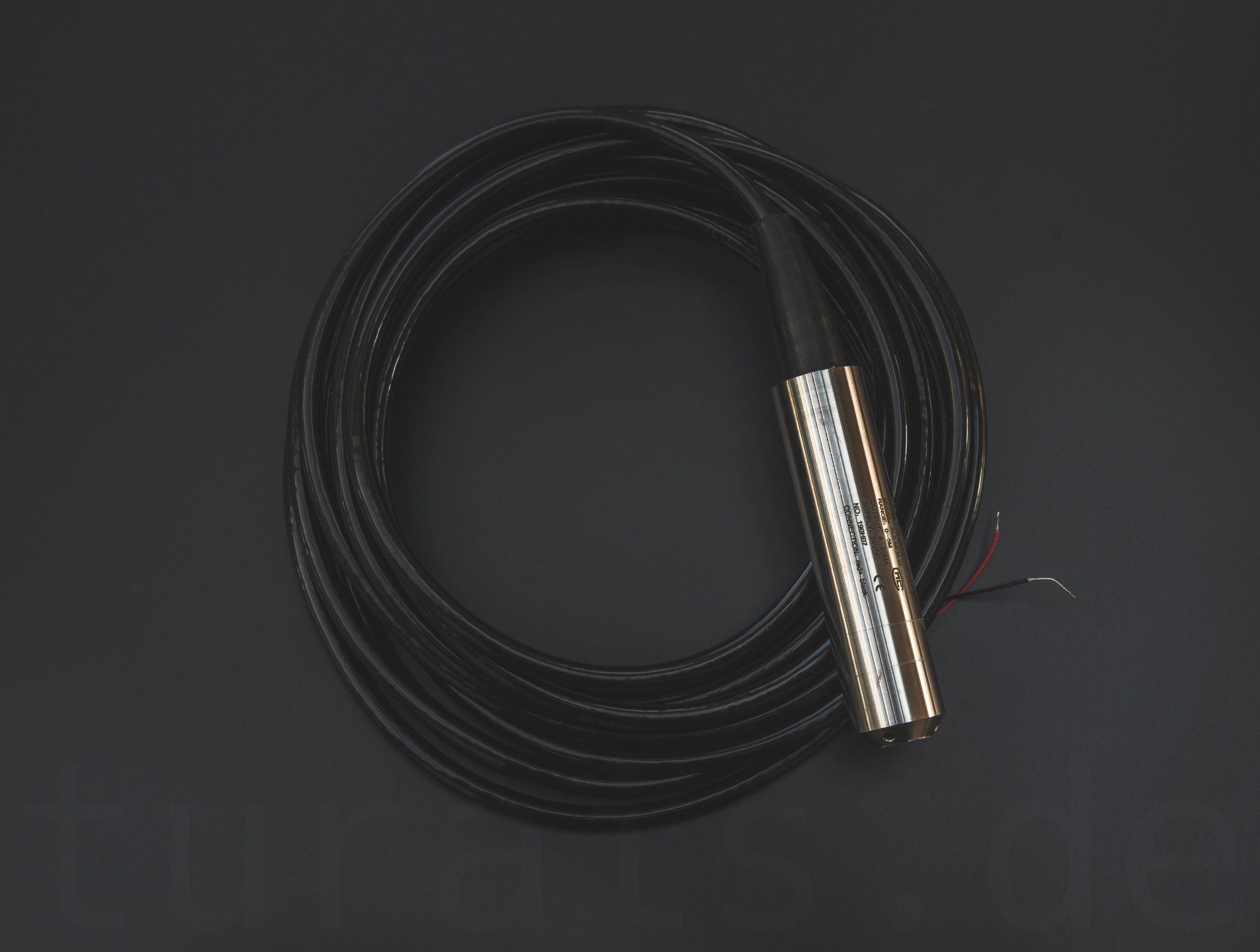
- TL231 or TL-231
- DC24 4-20mA Liquid Level Sensor
- TL136 or TL-136
- ASL-MP-2F
There are a bunch of Chinese brands that sell this sensor, they look almost identical but I can't tell you if this sensor is the same. But they all work with the same principal.
The TL231 Liquid Level Sensor works by sensing the pressure. The sensor, unlike other types of pressure sensor you'll find in your smartphone or the air pressure sensor BME280 from Bosch, works under water up to an depth of 5 meters.
The pressure in water changes linear with the depth. The deeper you go the more pressure you get. (Wikipedia Article: Link)
If you go 1 meter deep you get around ~0.1 bar more pressure. (Wikipedia Pascals Law)
The pressure at the sensor depends on the water above the sensor. This way you can interpret the values you get from the sensor as the water level in your tank/cistern.
The principle to read values are: The values are transmitted via current and not via voltage.
If you supply the sensor with 24V and have it in air and not underwater, the sensor will "consume" 4mA. If the pressure increases it will go linear up to 20mA.
Ideally 4mA would be 0m water above the sensor and 20mA would be 5m water above the sensor.
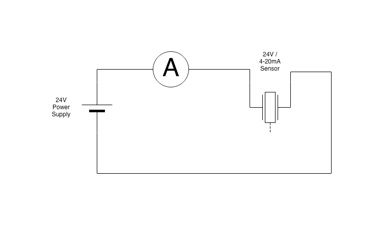
To read the current, for example for testing the sensor you can use an multimeter. You get those from Amazon for about 10EUR, and they're sufficient enough for testing.
Get some readings
There are three ways I find most practical to get readings:
- 250Ohm Resistor in series, then measure the voltage drop.
- HW-685 Current Sensing Module/
- INA219 Current Sensor, it is advertised to read with 0.8mA precision which is very good.
For automatically reading the pressure there is one basic principle. To read currents you need an resistor. Normally you don't want an resistor with high resistance in series but in this case the sensor behaves like an constant current source. It will regulate the current based on the pressure.
More on this technique here:

and: (Wikipedia Current Loop)
First I thought why not use an cheap module from Aliexpress for reading those currents. There are some available like the one I introduced in the blog article above. It's called HW-685 and of course you can get it from Aliexpress or from Amazon.
I had some problems with this module. And in my opinion its way too cumbersome to use it. If you decide to use it you need:
- Constant 5.0V Power Supply - It needs to be real constant, not like an USB Power supply. If your supply voltage changes overtime, so will your reading change. A solution would be to measure both supply voltage and the VOUT from this module to compensate.
- 24V Boost Converter from your supply voltage to 24V.
- Arduino or ESP8266 for reading the VOUT. I won't go into details here how to read analog voltages with your ESP8266 or Arduino.
More here:
Reading values with an Arduino
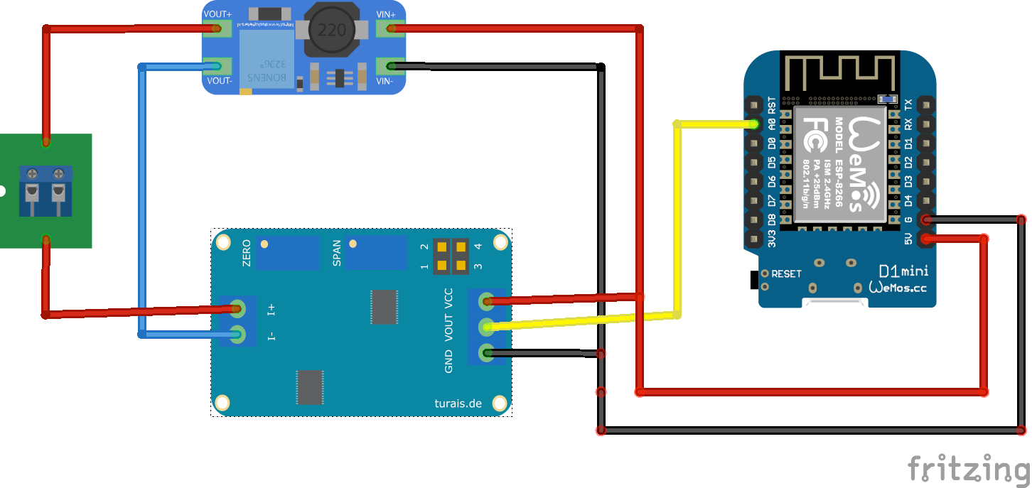
I used an ESP8266 namely an WEMOS D1 mini for testing. Later on I will change my current existing cistern level sensoring module based on an ultrasound sensor to this sensor.
To read the values with an Arduino you need:
- Resistor of about 160 Ohm.
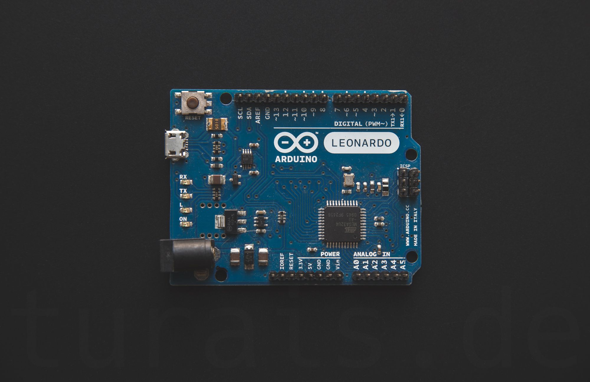
- Arduino or ESP8266 or an WEMOS D1 Mini.
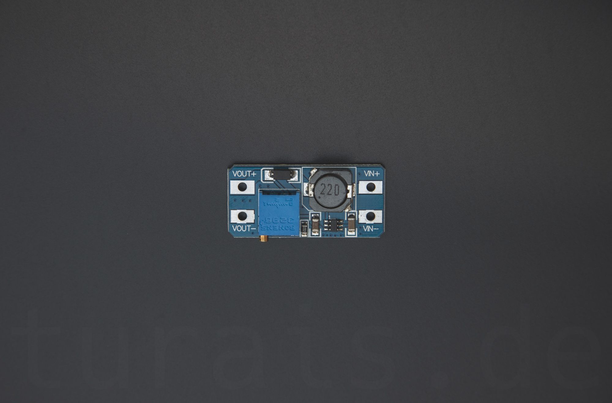
- MT3608 - Boost Converter to get 24V volts for your Liquid Level Sensor
- Liquid Level Sensor (Amazon, Aliexpress)
- Cables wires and a box to put it all in
Of course you need experience in soldering and so on.
Reading voltage drop at the 220Ohm resistor:
- at 4mA you will get about: U=R*I; U=160*4mA = 640mV
- at 20mA you will get about: U=R*I; U=160*20mA = 3200mV
This would be in the range of your ADC, for example the range of the WEMOS is 0V-3.3V. The ADC has an resolution of 10bits. Where at 3.3V you'll get an reading of 1023 and at 0V an reading of 0.
3.3V / 1023 = 3,22mV per unit
640mV => 199
3200mV => 994
994-199 = 795 units ... 5m depth would be 795 and 0 m 199 units.
A sensor failure would be above or below those values. This would get you around a resolution of about ~1cm. But the sensor itself is not so accurate I found that you can get readings with an accuracy of about +/- 10cm.
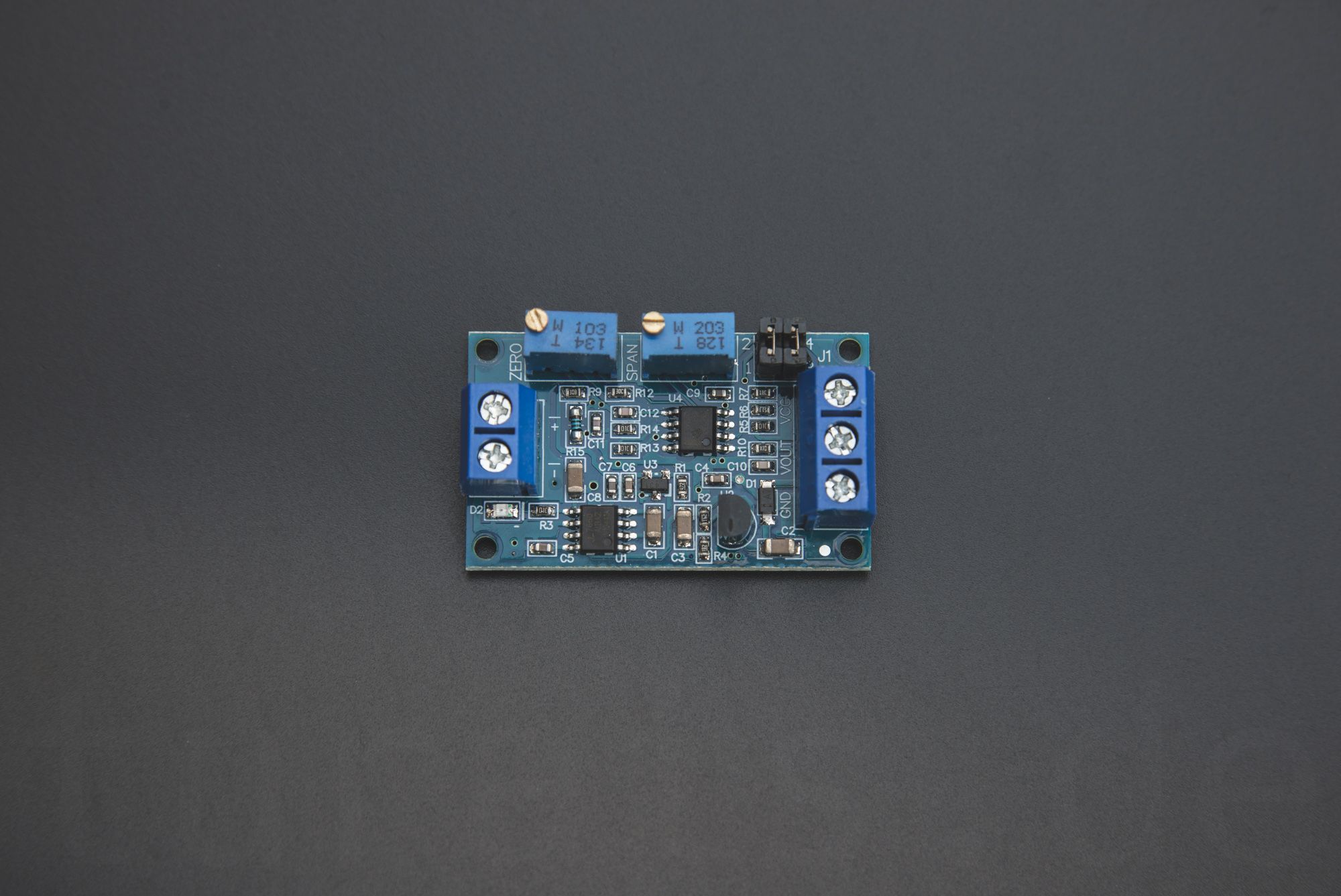
DFRobot Gravity Throw in Liquid Level Transmitter
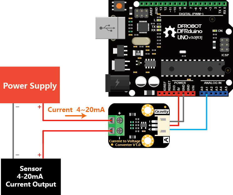
You can also use the DFRobot Gravity Current to Voltage Module. Here is the link to their wiki.
This module is basically a fancy 120R Resistor I told you about earlier. Its using a TP5551 OpAmp to read the voltage drop at the 120 Ohm resistor.
- You can get the Layout/Schematic of their module on Github. (Click)
- You can buy the Module here: (Click).
- Wiki from DFRobot for their kit. (Click).
Reading the sensor with commercial available Hardware
The 4-20mA current loop is an de facto industry standard. You can use an Siemens Logo! with an addon module for readings sensor data like this.
of course any other PLC with an possibility for a current loop works.
Also if you like you could use a commercial available process indicator. Get it on Amazon: (Click). For this setup I would recommend:
If you have any questions don't hesitate to write me an E-Mail or post an comment below!
If you press this Button it will Load Disqus-Comments. More on Disqus Privacy: Link